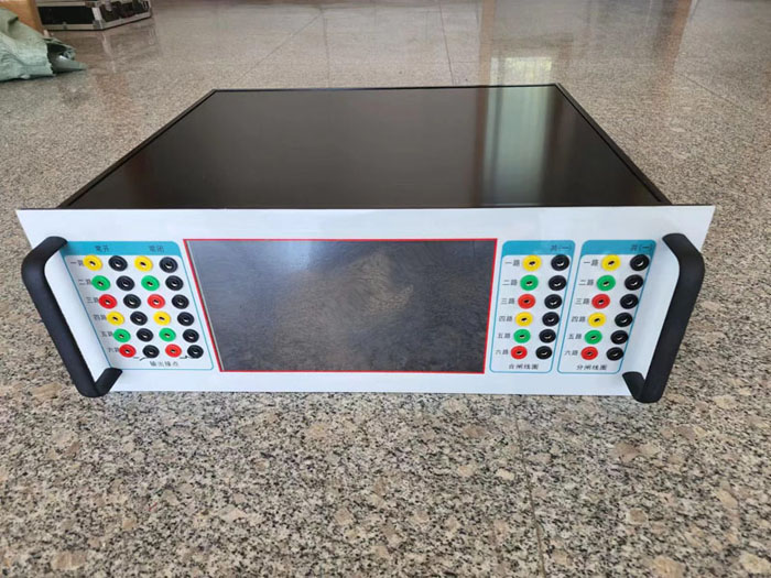
NXMK-VI Simulated Circuit Breaker Device (4U)
The NXMK-VI simulated circuit breaker system is primarily designed for comprehensive testing of relay protection devices and serves as a substitute for actual circuit breakers in various testing projects.
1.Device Overview
The NXMK-VI simulated circuit breaker system is primarily designed for comprehensive testing of relay protection devices and serves as a substitute for actual circuit breakers in various testing projects. It functions as an alternative equipment during transmission tests of integrated switchgear systems for relay protection and automation devices, featuring precise and reliable operation with unlimited actuation cycles. This significantly enhances test accuracy and completeness while minimizing actual circuit breaker operations, thereby extending service life. The simulation device can be used either in conjunction with relay protection calibration equipment or independently. Particularly in newly constructed power plants and substations where high-voltage circuit breakers require calibration or DC power supply installation, this system ensures test reliability free from external interference, effectively reducing commissioning time and improving testing efficiency. Its application proves highly cost-effective for manufacturers and research institutions. Additional configurations may be customized based on specific requirements. (This device is specifically designed for simulated closing and opening operations of permanent magnet circuit breakers.)
2.Main Features
1) Six switch contacts corresponding to opening/closing coils;
2) Dual sets of opening/closing coils available;
3) Built-in manual operation function;
4) Adjustable resistance levels for opening/closing coils;
5) Multiple time slots selectable for opening/closing duration;
6) Multiple pairs of open contacts for position output;
7) Multiple pairs of open contacts for pulse output;
8) Microcontroller-based system with upgrade capability for intelligent operation;
9) High-performance hardware platform featuring industrial-grade standard components and military-grade core components, ensuring superior device quality.
10) (Positive voltage on the closing coil triggers closing, negative voltage triggers opening)
3.Key technical parameters
1)Power supply voltage: AC220V ±10% 50Hz, with operating current below 0.5A.
2)Output quantity nodes: The circuit breaker position output contacts consist of 6 normally open and 6 normally closed pairs, operating independently. These are divided into two groups corresponding to the circuit breaker tripping coil. Tripping and closing time: Adjustable within the range of 10ms to 1000ms, with an allowable error of ±5ms.
3)Opening and closing currents (coil resistance): ∞Ω, 880Ω,440Ω,220Ω,110Ω,44Ω
4)Manual closing and opening: When operating via the 'Manual Close' and 'Manual Open' buttons on the touchscreen, no current flows through the opening/closing coils of the circuit breaker simulation device.
5)Output node: Connection capacity: DC 220V/0.5A, AC 220V/5A.
6)Switching pulse output: Provides six sets of output nodes with a 1000-millisecond switching duration.
7)Equipped with a 10-inch color display screen, devoid of any mechanical transfer switches or buttons, thereby extending service life.
8)Using 4U chassis facilitates panel assembly experiments.