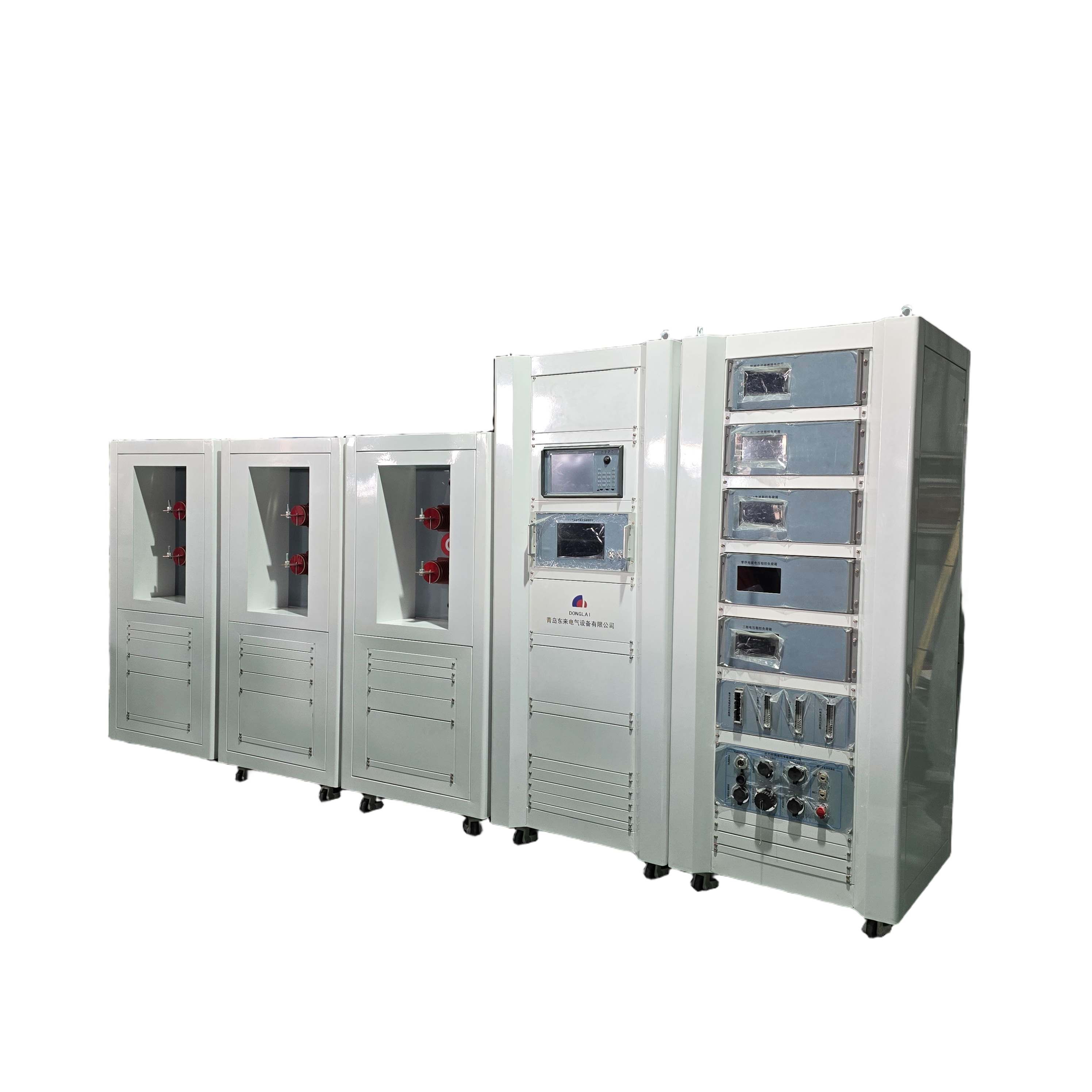
NXRH-1000-10000Testing System for Integrated Primary and Secondary Integration Equipment
As State Grid Corporation advances the construction and upgrading of its distribution networks, a large number of distribution automation terminals have been integrated into these networks.
I、Introduction
According to the "Guiding Opinions on Accelerating the Construction and Upgrading of Distribution Networks" (NDRC Energy [2015] No.1899) issued by the National Development and Reform Commission, it explicitly requires strengthening the development of distribution automation systems, with the coverage rate of distribution automation set at 90% by 2020.
With the advancement of distribution network construction and renovation by State Grid Corporation, a large number of distribution automation terminals have been integrated into the distribution networks, making the automation systems increasingly sophisticated. To standardize development, State Grid has established the principle of "unified planning, unified standards, and unified construction," and issued regulatory documents including the Technical Guidelines for Distribution Automation, Functional Specifications for Integrated Intelligent Technology Support Systems for Distribution Network Control, Draft Standardized Design for Distribution Automation Terminals, and Draft Standardized Design for Integrated Primary-Secondary Terminals, providing detailed guidance for establishing a unified set of terminal equipment and an integrated testing platform for primary and secondary systems.
1.1 analysis of current status
The main issues currently encountered by testing institutions at all levels in integrated primary and secondary testing include:
The inspection efficiency remains low. Although the number of complete sets of equipment tendered by State Grid has been increasing annually, there are few corresponding inspection platforms available. Currently, inspection agencies at all levels still rely primarily on manual methods for testing these complete sets of equipment, resulting in poor inspection efficiency.
The current manual detection methods used in testing are unreliable and have the following drawbacks.
(1)Due to the integration of primary and secondary detection processes, specifications such as first-order accuracy, set accuracy, set functionality, second-order accuracy, and functionality must be defined; the operational procedure is highly complex, requires involvement of multiple personnel, is heavily influenced by subjective factors, and cannot achieve comprehensive testing;
(2) The testing process lacks traceability, necessitates continuous monitoring by staff throughout, and cannot automatically generate test records;
(3) The tester's output power is limited, unable to deliver high voltage or high current, making complete functional and performance testing challenging.
1、
1) Testing protocols for distribution automation terminals before supply and upon delivery;
2) "State Grid Corporation's Professional Testing Outline for Integrated Primary/Secondary Column Switches and Ring Network Boxes";
3) Technical Specifications for Distribution Automation Terminals (Trial);
4) Testing protocols for distribution automation terminals before supply and upon delivery;
5) Cybersecurity Protection Solutions for Distribution Automation Systems;
6) Technical Specifications for Smart Distribution Transformer Terminals (Trial);
7) Functional Specifications for Main Stations in Distribution Automation Systems (Trial);
8) Professional Testing Protocols for Main Station Integration into Distribution Automation Systems;
9) Technical Specifications for Smart Distribution Transformer Terminals (Trial);
10) Implementation Guidelines for DLT634.5101-2002 in Distribution Automation Systems (Trial);
11) Implementation Guidelines for DLT634.5104-2009 in Distribution Automation Systems (Trial);
12) GB/T 13729-2002 Remote Control Terminal Equipment;
13) DL/T 630-1997 Technical Requirements for AC Sampling Remote Control Terminals;
14) DL/T 721-2013 Distributed Automation Remote Terminals;
15) "Safety Protection Regulations for Power Monitoring Systems" (State Development and Reform Commission Order No.14,2014);
16) "Overall Safety Protection Plans and Evaluation Standards for Power Monitoring Systems" (Guo Neng Anquan [2015] No.36);
17) DL/T 1080.13-2012 System Interfaces for Integrated Distribution Management in Power Enterprises;
18) Q/GDW626-2011 "Management Specifications for Operation and Maintenance of Distribution Automation Systems"
19) Q/GDW1807-2012 "Typical Design Specifications for Terminal Communication Access Networks"
2、Platform Composition
The system consists of a primary-secondary fusion detection platform, including detection servers and software components.
The primary and secondary fusion detection platform consists of a control cabinet and a high-voltage test bench.
The primary and secondary integration testing platform consists of a control cabinet and a high-voltage test bench. The control cabinet serves as the core component of the entire system, responsible for signal control and output, and primarily comprises a signal source, data acquisition device, power amplifier, clock source, and instrument transformer testing unit. The high-voltage test bench includes a voltage-raising transformer, current-raising transformer, standard voltage transformer, and standard current transformer.
The control cabinet consists of a primary and a secondary integration unit:
(1)signal source
Primarily receives control commands and instructions issued by automation software, and performs functions such as outputting voltage and current signals as well as acquiring switch signals.
(2) Extraction Device
Verify the AC signals from the ring main unit/pole-mounted switch to test its primary accuracy. Additionally, collect data from the standard transformers on the high-voltage test bench, compare it with the output signal from the source, calculate the error; if the error exceeds the allowable limit, halt the output and trigger an alarm.
(3) Power amplifier
Amplify and output the signals from the three signal sources in real time.
(4) Waveform Monitoring Integrated System
The primary purpose is to verify the accuracy of power source output values, provide waveform recording functionality, and ensure that all error calculations compare against the system's monitored values rather than the source values, thereby enhancing test accuracy.
Composition of the High Voltage Test Bench:
(1) Step-up device
It employs a high-precision 10 kV self-elevating voltage transformer with a accuracy class of 0.02 to deliver a 10 kV output voltage. The device is housed within a high-voltage test bench and features external terminal connections.
(2) Upstream Device
A high-precision current transformer with a ratio of 600/5 and accuracy class 0.02 is employed, delivering a maximum output current of 1000 A. The device is installed within a high-voltage test bench and equipped with external terminal connections.
(3)standard potential transformer
Using a high-precision 10 kV self-diverging voltage transformer with a accuracy class of 0.02, this system converts 10 kV voltage into a 100 V output signal. When paired with a data acquisition device, it monitors whether the platform's voltage output is normal.
(4) Standard Current Transformer
A high-precision current transformer with a ratio of 600:5 and accuracy class 0.02 is employed to convert the primary current signal into a secondary current signal. When combined with a data acquisition device, it enables monitoring of whether the platform's current output operates normally.
(5) Standard Zero-Order Current Transformer
A standard device for detecting zero-sequence current in complete sets of equipment, utilizing a high-precision zero-sequence current transformer with a transformation ratio of 100/5.
3、Testing Process
4、system function
4.1 Primary and Secondary Integration Detection Process
4.2 Primary Telemetry Accuracy Test
Ø Phase voltage detection: Connect the primary equipment to the output terminal of the high-voltage test bench and connect its terminal block to the transformer testing device in the control cabinet. The system automatically controls power supply output, measures both the voltage values from the waveform monitoring device and the transformer testing device, calculates the error, and determines compliance. The software supports PT ratio configuration.
Ø Phase current detection: Connect the primary equipment to the output terminal of the high-voltage test bench and connect its terminal block to the transformer testing unit in the control cabinet. The system automatically controls power supply output, measures current values from both the waveform monitoring device and the transformer testing unit, calculates the error, and determines compliance. The software supports CT ratio configuration.
Ø Zero-sequence voltage detection: Connect the primary equipment to the output terminal of the high-voltage test bench and connect its terminal block to the transformer testing unit in the control cabinet. The system automatically controls the power supply to deliver zero-sequence voltage; by measuring the zero-sequence voltage values from both the waveform monitoring device and the transformer testing unit, it calculates the error and determines compliance. The software supports setting the zero-sequence voltage transformation ratio.
Ø Zero-sequence current detection: Connect the primary equipment to the output terminal of the high-voltage test bench and connect its terminal block to the transformer testing device in the control cabinet. The system automatically controls the power supply to deliver zero-sequence current; by measuring the zero-sequence current values from both the waveform monitoring device and the transformer testing device, it calculates the error and determines compliance. The software supports setting the zero-sequence current ratio.
Ø Phase voltage angle detection: Connect the primary equipment to the output terminal of the high-voltage test bench and connect its terminal block to the transformer testing device in the control cabinet. The system automatically controls the power supply to deliver voltages with different phase angles; by measuring both the voltage angle values from the waveform monitoring device and those from the transformer testing device, it calculates the error and determines compliance.
Ø Phase current angle detection: Connect the primary equipment to the output terminal of the high-voltage test bench and connect its terminal block to the transformer testing device in the control cabinet. The system automatically controls the power source to deliver currents with varying phase angles; by measuring both the current angle values from the waveform monitoring device and those from the transformer testing device, it calculates the error and determines compliance.
Ø Zero-sequence voltage angle detection: Connect the primary equipment to the output terminal of the high-voltage test bench and connect its terminal block to the transformer testing unit in the control cabinet. The system automatically generates zero-sequence voltages with varying phase angles from the power supply; by measuring both the zero-sequence voltage angle values from the waveform monitoring device and those from the transformer testing unit, the system calculates the error and determines compliance.5、系统指标
5.1Power Source Specifications for Distribution Terminal Appliances
l Power Supply: AC 380V@50Hz
l Rated power: ≥4 kW (single-phase)
l Output range: Voltage: 0–250 V; Current: 0–30 A
l Range: Voltage: 57V,100V,220V; Current: 1A,5A,20A
l Fineness adjustment: 0.002% RG
l Accuracy: 0.02% RG
l Stability: 0.01%/1 min
l Distortion: ≤0.2% (under non-capacitive load)
l Phase output range: 0–359.9
l Phase adjustment precision: 0.01
l Frequency range: 45 Hz to 65 Hz
l Frequency adjustment precision: 0.01 Hz
l Power Factor Adjustment Range: -1~0~+1;
l Power Factor Resolution: 0.0001;
l Active Output Accuracy:Class 0.05
l Reactive Power Output Accuracy:Class 0.05
l Number of voltage and current harmonic settings:2~21st order;
l Voltage and current harmonic content:0~40%
l Harmonic Phase: 0–359.99 (adjustable)
5.2Indicators generated by the primary and secondary integration platforms
l Voltage Output Range: 0–10000 V
l Output current range: Voltage: 0–1000 A
l Accuracy: 0.05% RG
l Response time: less than 1 second
5.3Test Efficiency Indicator
l Detect simultaneously
The distribution terminal, combined with primary and secondary systems, can perform simultaneous detection.
l No less than 4 sets per day; including one test, two tests, and a complete set of tests.
5.4 size requirement
l Test Device Dimensions
n Complete control cabinet: dimensions 600 × 800 × 1865 mm
n High-voltage test bench: dimensions 900 × 800 × 1020 mm
n Terminal control cabinet: dimensions 600 × 800 × 1865 mm
n Terminal wiring assembly: dimensions 800 × 800 × 1000 mm
l Site requirements: Minimum area of 40 square meters; can be located in the testing hall of the Testing and Maintenance Branch.
5.5 Power Supply and Personnel Requirements
l Power specifications: AC 3×220V/380V (Y) ±10%
l Capacity: Many models have a capacity of 60A
l Primary and secondary fusion detection requires two dedicated testing personnel.
5.6 Charging Standards and Benefits
6、system configuration
name | serial number | component | Specification Parameters | quantity | Remarks |
workbench | 1 | computer |
| 1set | With Mouse and Keyboard |
2 | switch | TL-SG1032,32-pin port | 1single |
| |
Complete Control Cabinet Set | 1 | signal source | 6-channel analog output | 1set |
|
2 | Voltage Amplifier | 3*(0~125V),3500VA | 3single |
| |
3 | Current Amplifier | 3*(0~30A),3500VA | 3single |
| |
4 | Extraction Device | 8-channel voltage acquisition, 8-channel current acquisition, accuracy class 0.05 | 1set |
| |
5 | exchange board | TL-SG1032,32-pin port | 1single |
| |
Complete set of high-voltage test benches | 1 | Step-up device | Step-up transformer ratio: 0.12/12 kV, Class 0.02S | 3single |
|
2 | Upstream Device | Upstream flow ratio: 600/5; Class: 0.02S | 3single |
| |
3 | potential transformer | Collection voltage ratio: 10/0.1 kV, Class 0.02S | 1cover | With zero-sequence voltage | |
4 | current transformer | Collection transformer ratio: 600/5; Class: 0.02S | 3single |
| |
5 | Zero-sequence voltage transformer | Collection ratio: 100/5; Class: 0.02S | 1single |
| |
2 | NI Data Acquisition Board | Sampling frequency: 100 kHz; 16-channel analog signal | 1set |
| |
4 | switch | TL-SG1032,32-pin port | 1single |
| |
5 | Serial Server | gorge line | 1set |
| |
accessory | 1 | high-voltage cable | High-voltage cable testing line | 1cover |
|
3 | Ethernet cable |
| several |