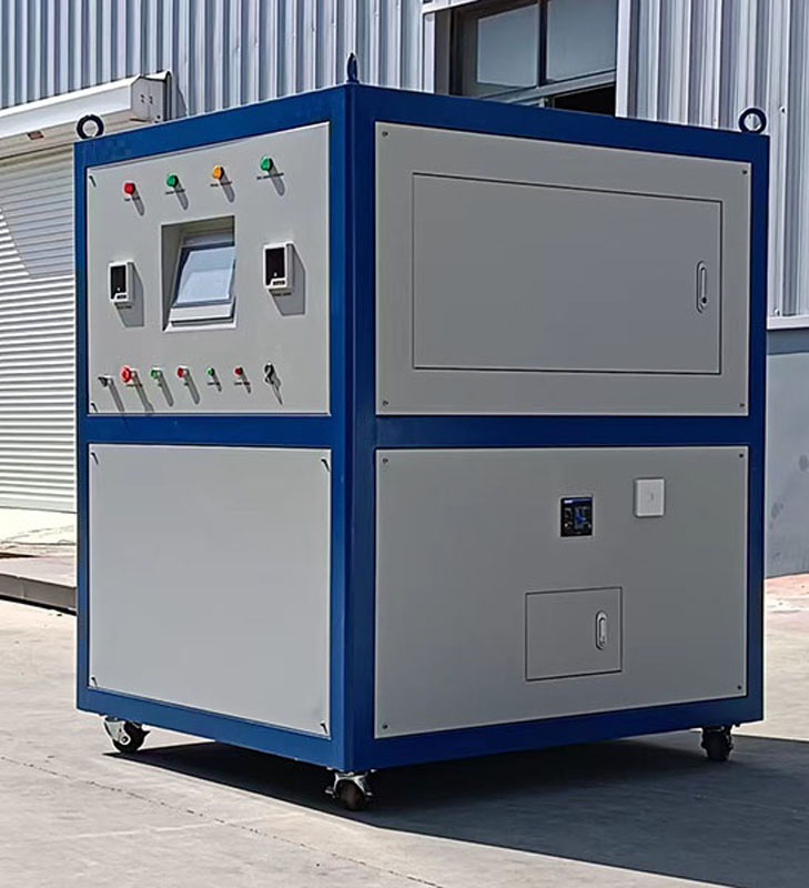
NX-5000Q Fully Automatic High Current Device with Temperature Rise Monitoring
The NX-5000Q fully automatic temperature rise high-current system features a low-power, high-capacity voltage regulator and a converter constructed with high-permeability iron cores for its fully automatic temperature rise device.
The NX-5000Q Fully Automatic Temperature Rise High Current System features a low-power, high-capacity voltage regulator and converter constructed with high-permeability iron cores, delivering advantages such as high output power, compact size, and lightweight design. Primarily used for temperature rise testing in high-voltage switchgear, low-voltage switchgear, busbars, current transformers, disconnectors, electrical hardware assemblies, copper-clad steel materials, and other advanced materials. Applications include thermal relay testing, motor protection devices, contactors, circuit breakers, air switches, switchgear systems, protective panel calibration, busbar assemblies, and cable insulation evaluation.
The fully automatic temperature warming and heating device is primarily composed of an AC power distribution unit, voltage regulation transformer, converter, power compensation assembly, drive control unit, data acquisition unit, human-machine interface, microcomputer control system, temperature acquisition unit, and configuration software.
I. Main Functional Features:
1) Equipped with a high-performance industrial PC featuring programmable logic controller (PLC) as the central processor, it performs real-time AC signal scanning to achieve comprehensive monitoring and closed-loop control. The system incorporates password-based access management, restricting operations to authorized personnel.
2) Operated via imported PC with true-to-life color LCD touchscreen, it utilizes fieldbus-compatible smart sensors for fully digital data transmission. The display unit employs touch-sensitive color LCD screens with intuitive Chinese menus, ensuring clear interfaces and effortless operation. Testing requires no external peripherals, featuring fully automated control and user-friendly operation for quick results.
3) The instrument supports both automatic and manual testing modes, requiring only simple configuration of test current and duration. It includes an automatic current stabilization system.
4) Target current settings eliminate manual monitoring – simply define test parameters, current values, and step increments to bypass tedious tasks like manual voltage adjustment, data logging, and curve plotting. This reduces labor intensity while improving efficiency, with post-test data readily accessible via computer.
5) Features automatic alarm functions for exceeding limits, along with reliable self-protection against overheating, overcurrent, overvoltage, and short circuits. AC voltage regulation employs dual safeguards: microcomputer-based automatic protection and mechanical limit switches to ensure stable current supply, enhancing product safety and reliability.
6) User-friendly interface with intuitive software operation.
7) Automatic adjustment of AC current source.
8) Customizable test modules according to user requirements with lifetime free software upgrades.
9) Equipped with a 64-channel temperature measurement module (up to 200 test temperature points optional).
10) Integrated power compensation system. 11) Data export functionality allowing device data to be stored on computers via USB drives for further processing or printing.
II. Technical Parameters
Model | NX-5000QFully Automated High Current System with Temperature Rise Monitoring | |
*High current output | AC single-phase 5000A | |
circuit method | Special Process Contact-Type Electric Voltage Regulator | |
AC input | Phase line | 2Φ +G |
Voltage | 380V±10%,50Hz±2% | |
input currenton | 131A After compensation, below 20A | |
output | phase line | two-phase |
voltage | 0-10 automatic conversion based on load settings | |
current | The AC0-5000A features continuous adjustable speed with stepless speed regulation; it offers two output modes: manual mode and automatic mode. | |
rated capacity | 60kVA | |
steady flow accuracy | output(current)≤±0.5% | |
leading-out terminal | binding post | |
protection | The electronic circuit rapidly detects overvoltage, overcurrent, overheating, phase loss, and other conditions to activate automatic tripping protection and alarm devices. The voltage and current are zero in non-test states | |
precision | source effect | 03 Rated Value |
time drift | 1 Rated value | |
thermophilic swelling | ≤0.04% rated value/°C | |
Display settings | True Color Display | 7-inch, 10-inch, or 15-inch polyamide screens may be used, or external computer control can be employed. |
Current Display | True color liquid crystal display and digital instrument (6-digit digital display, display accuracy 0.1A, display error: ≤0.2% ± 1 digit) | |
Adjust settings | Current (software setting) | |
system | overall efficiency | ≥90% |
insulation impedance | AC 1800V for 1 minute, 20 megohms | |
cooling equipment | forced fan cooling | |
noise | ﹤60dB(1 mm in front of the machine) | |
Transformer accuracy | 0.2S级 | |
levels of protection | IP20 | |
working condition | operate mode | Long-term temperature rise test exceeding 8 hours |
temperature | -10℃-50℃ | |
humidity | 0-90%(Non-condensed state) | |
above sea level | below 1500m | |
appearance | structure | Complete or partial |
| size | Customize on demand |
| weight | Customize as needed |
| busbar | Output calculated at 1.2 current per square meter, followed by |
Temperature inspection | 8-channel module | Temperature measurement can be performed in 8-channel, 16-channel, 24-channel, 32-channel, 40-channel... up to 200-channel configurations as required. |
Class A thermistor | PT1000 or thermocouple | |
New Features
1. Includes switches from power supply to voltage regulator input and from voltage regulator output to current booster input (i.e., front-stage closing and rear-stage closing), corresponding to rear-stage opening and front-stage opening; emergency stop function; mutual interlock mechanisms (front-stage failure prevents rear-stage closing; rear-stage failure prevents front-stage opening!).
2. Features zero-position interlock functionality for voltage regulators.
3. The current booster body has a central opening for high-current output that allows direct conductor penetration, facilitating experiments and live current testing.
4. Special construction effectively controls eddy current heating in the booster's support frame and metal casing.
5. High-strength wheels at the base enable easy mobility.
6. Wireless control system includes front-stage closing, rear-stage closing, current boosting/downgrading, rear-stage opening, front-stage opening, and emergency stop buttons, meeting interlock requirements (front-stage failure prevents rear-stage closing; rear-stage failure prevents front-stage opening). All controls are remote-operable, with wireless components integrated into the voltage/current integrated control panel for intuitive display.
7. Optional wireless power supply.
8. LCD display monitors power supply voltage/current, voltage/current at voltage regulator output, and current booster output.
9. Power failure protection: During current boosting tests, sudden power loss will automatically reset the voltage regulator motor to zero position (with zero position indicator) after manual air switch closure on control cabinet panel. Only then can front-stage closing, rear-stage closing, current boosting/downgrading operations proceed, strictly preventing abrupt power supply interruption under inrush load conditions.
10. Users may select from 7-inch, 10-inch, or 15-inch screens or computer host control systems based on their requirements.
1.1 Action Time Test: 0.001–99999.999 seconds
1.2 1.2 Fully automatic current control with adjustable increment
1.3 1.3 64°C temperature monitoring The temperature range of the test device can be customized as required.
11. Automatic and manual operation.
1.1 Real-time display of current, voltage, transformer temperatures, and multi-point temperatures of test specimens during testing processes, presented in tabular and graphical formats. Data can be transferred and stored on other computers for further analysis and archiving. Data is formatted in Excel spreadsheets for easy conversion between charts, curves, and numerical data, with text documents maintained in Word format.
1.2 Adjustable test current settings ensure stable and reliable operation unaffected by system or external factors.
1.3 Customizable allowable temperatures for test specimens, with the system automatically adjusting maximum current output. When the specimen reaches the preset temperature, it displays and records the maximum operating current at that moment – specifically the maximum operating current of the busbar under highest allowable temperature (or maximum operating current at set temperature).
1.4 Provides minimum/maximum current and temperature values for transformers and test specimens, featuring automatic alarm functions when exceeding predefined thresholds. Equipped with reliable self-protection mechanisms against overheating, overcurrent, overvoltage, and short circuits.
1.5 Enables automated repeated high-current temperature rise tests for identical specimens, allowing configuration of test cycles, current levels, intervals, current ramp rates, and maximum current duration within allowable temperature ranges. The system automatically completes all post-test operations, supporting cyclic testing capabilities. 1.6 All parameters can be preset through a touchscreen interface prior to testing, ensuring intuitive operation.
1.7 Provides essential protection and audible/visual alarm signals when detecting overcurrent, overvoltage, short circuits, overheating, or voltage loss. For alarm factors that do not require immediate destructive action on the test equipment, an audio-visual alarm can be triggered. Operators should assess the situation based on actual conditions upon receiving the alarm and take appropriate measures. Within a specified time after the alarm is activated, if no one is present, the equipment will automatically shut down.
Equipment Data Acquisition via MES System
1) Equipment data acquisition information includes: status information, test information, processing information, alarm information, quality information, energy information, etc.
2) Reserve Ethernet ports for the MES system to be used by equipment. The equipment communication interfaces must incorporate electrostatic protection, overvoltage protection, and lightning/surge protection designs.
3) Supports OPC2.0 and OPC3.0 interface standards; 4) The device is equipped with an industrial PC, requiring data acquisition information to be stored in structured data format on local or server databases.
5) The equipment manufacturer provides data acquisition information (network configuration, communication protocols, data acquisition parameters, and user manuals).
6) Reference for inspection test equipment system architecture (separation of host computer and database server).
To support data collection and interaction requirements for cloud-based and LAN server-based property management platforms, the detection equipment utilizes databases such as MySQL and SQL Server to store test parameters, standards, and device status. Data can be published to the property management platform via the MQTT protocol. Upon receiving the data, the platform pushes the detection results back to the equipment and features a "Cloud Connector" linking function.
1.The detection equipment features data storage capabilities, with databases including conventional options such as MySQL and SQL Server.
2.The testing station actively pushes data, with the pushed format including but not limited to: testing institution ID, testing station, sampling plan number, material category, testing items, key parameters, measured values, and test results. Additionally, database information is made available for data retrieval module calls within the testing system.
3.Information such as sampling plan number or time period can be manually entered through the human-machine interface of the host computer.
The content of image-type data transmission includes but is not limited to: sampling plan number, experimental project, feature value 1, feature value 2, etc. (The above content may be adjusted as required).
Image storage method: The system detects that images are stored in binary data stream format in the database. Generated images should be saved in JPG or PNG format, with naming rules and storage location settings customizable as required. The image resolution generated is approximately 833*304.
It can provide database dictionary and database association diagram.
It can provide data retrieval logic for various detection item databases.
It is not merely a database and software, but a robust independently developed solution.