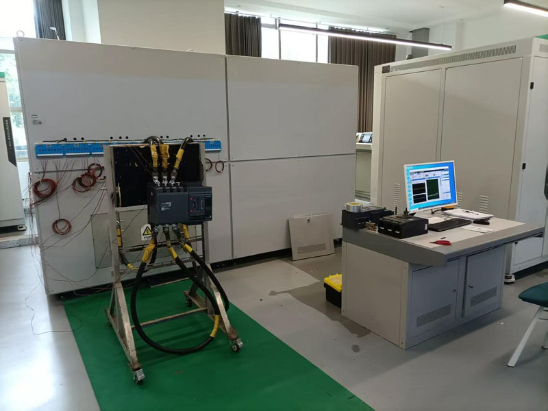
NX-12000Impact-resistant high-current generator
The NX-12000 Impact-Tolerant High Current Generator is designed in accordance with national standards for short-duration high current impulse withstand testing equipment, primarily applicable to circuit breakers, power cables, and similar applications.
1. Basis for user application:
The NX-12000 Impact-Tolerant High Current Generator complies with national standards for short-duration high current impulse testing equipment. It is primarily used for current withstand testing of products including circuit breakers, current transformers, power cables, metal fittings, fault indicators, and power extraction devices, as well as long-duration and short-duration breaker tests. Note that specifications vary depending on hardware/software configurations and power ratings; manufacturer consultation is required for detailed specifications.
Maximum output current: 5 kA for single-phase
Maximum current output duration: 4 seconds
Sample length: Circuit breaker, output line as required.
(Reducing the length can lower power requirements)
2. Citation standards:
GB/T9327-2008 (Test Methods and Requirements for Crimping and Mechanical Connectors Used in Power Cable Conductors with Rated Voltage of 35kV (Um-40.5kV) and Below)
B/T8979-2006 "Residual Current Circuit Breakers with or Without Overload Protection"
GB/T 11022-2011 "Common Technical Requirements for High Voltage Switchgear and Control Equipment Standards"
GB 20120-2006 "Electrical Installation Engineering-Electrical Equipment Handover Test Standards"
GB/T14808-2001 "AC High Voltage Contactors and Motor Starters Based on Contactors" GB/T11022-2011 "Common Technical Requirements for High Voltage Switchgear and Control Equipment Standards"
JB8739-2015 "Mine Explosion-Proof High Voltage Distribution Equipment" MT871-2011 "Mine Explosion-Proof Low Voltage AC Vacuum Feeder Switches"
MT111-2011 "Mine Explosion-Proof Low Voltage AC Vacuum Electromagnetic Starters" JB3956-1985 "Mine Explosion-Proof Feeder Switches"
GB14048.1-2012 "General Requirements for Low Voltage Switchgear and Control Equipment"
GB 14048.2-2008 "Circuit Breakers"
GB 14048.3-2008 "Switches, Isolators, Switch-Isolator Combinations, and Fuses"
GB 14048.4-2010 "Contactors and Motor Starters" 14048.5-2008 Electrical Appliances and Switching Elements for Control Circuits;
GB10963.1-2005 Overcurrent Protection Circuit Breakers for Household and Similar Applications; DL/T 572-2010 Operating Procedures for Power Transformers;
JB/T 7070.1-2002 Guidelines for Voltage Regulator Testing;
JB 8749-1998 General Technical Requirements for Voltage Regulators
3.Main Technical Specifications
1. Main constituent components
Serial Number | Name | Model Number | quantity | Unit | Parameter Description |
1 | Current source shunt current booster (short-circuit overload type) | NX-12KA | 1 | Tai | Power: 120KVA |
2 | Current source voltage regulator | NX-150KVA | 1 | Tai | 功率:150KVA 电压:420V |
3 | Mutual Inductor |
| 1 | Tai | 0.2 Ensure current accuracy |
4 | NI Integrated Board |
| 1 | Tai | Output control, waveform data acquisition, current acquisition, time acquisition |
5 | Bipolar start-up circuit |
| 1 | set |
|
6 | Advantech Industrial PC |
| 1 | Tai | Output control waveform display |
7 | Servo motor |
| 1 |
|
|
8 | Sports board card |
| 1 |
|
|
2. Technical Parameters
Input voltage: AC380V ±10% two-phase system with neutral line
Maximum output AC current: 12kA for single-phase.
Maximum output open-circuit voltage: 0~10V
Output display: NI board acquisition, capable of displaying current values and current waveforms.Accuracy Requirements:
Source effect: ≤0.3% of the rated value
Time drift: ≤1% of rated value
Temperature drift: ≤0.04% rated value/°C
Load effect: ≤1% of rated value (the rate of change in output voltage caused solely by the variation of output current from zero to rated value)
Ripple voltage: ≤1% of rated value +10mV.
Route adjustment rate: 0.1%
Load adjustment rate: 0.1%
Sampling section:
A 0.2-class high-precision Rogowski coil was adopted, ensuring high-precision performance in current data and waveform.
Output display :
Primary display mode: The voltmeter features a 6.5-digit LCD display, and the ammeter also has a 6.5-digit LCD display.
3. Hardware Parameters
Rated capacity | 150KVA |
Phase number | Single-phase |
Input voltage/current | 380V/400A(Instantaneous current) |
output voltage | 0-10V |
output(current) | 0-12000A |
Frequency | 50Hz |
Output angle | Random |
Motor power | 200W servo motor |
Insulation grade | Class B |
Insulation resistance | 5MΩ |
Withstand Voltage Test | 2000V/min |
waveform distortion | ≤0.1% |
cooling-down method | Natural cooling |

