NX-3000Q Current transformer temperature rise
The temperature rise test of NX-3000Q current transformer is fully automated in compliance with national electrical standards.
The temperature rise test for NX-3000Q current transformers is fully automated in compliance with China's national standard "GB1206 Current Transformer" and State Grid Corporation of China's technical specification "Q/GDW 1572 Technical Specifications for Metering Current Transformers". The system automatically adjusts the electronic current booster to target test current levels based on the rated current of connected transformers, continuously monitoring core temperature, winding joint temperature, and ambient temperature throughout the process. Upon achieving thermal stability, it automatically disconnects output current while measuring the winding DC resistance of transformer coils. By comparing current resistance values with baseline measurements, the system calculates both the maximum winding temperature post-thermal stabilization and the highest temperature rise during testing.
1. Characteristics of the experimental apparatus
1)The 21-inch all-in-one machine is equipped with a host computer featuring dedicated testing software and utilizes a programmable logic controller (PLC) as the central processor. It performs real-time scanning of AC signals to achieve comprehensive monitoring and closed-loop control, while incorporating password-based access management. Only authorized personnel with corresponding operational permissions can perform specific functions.
2)Intelligent sensors utilizing fieldbus technology are employed to achieve fully digital data transmission. The display operation unit features a touch-sensitive color LCD screen with a full Chinese menu, offering a clear and intuitive interface for simple and convenient operation. Testing requires no external auxiliary equipment, featuring fully automated control and foolproof operation, ensuring rapid, straightforward, and user-friendly performance.
3)The device is equipped with an adjustable load, allowing manual switching of secondary loads based on the rated capacity of the current transformer.
4) All temperature rise data do not require manual calculation, as the software backend automatically completes the process.
5) Comprehensive protection features include overvoltage, overcurrent, and overheating protection with corresponding alerts.
6) The device is equipped with a DC resistance tester. After the heating process concludes, it automatically disconnects the secondary load box and switches to the DC resistance tester for measuring the cooling resistance of the secondary winding, eliminating the need for wire replacement during the test.
7) Customizable test modules based on user requirements with lifetime free software upgrades 8) Features 16-channel temperature monitoring (customizable)
2.Key component parameters
2.1 Output current of DC resistance measurement module: Automatic settings for 5mA, 40mA, 200mA, 1A,5A, and 10A ranges; Measurement ranges: 100Ω-200KΩ (<5mA range); 1Ω-500Ω (40mA range); 100mΩ-100Ω (200mA range); 5mΩ-20Ω (1A range); 1mΩ-4Ω (5A range); 0.2mΩ-2Ω (10A range).
Resolution: no less than 0.1 μΩ; Accuracy: no less than 0.2%.
2.2 Temperature Measurement Module: Measurement method: Thermocouple channels: 16 channels.
Measurement Accuracy: 0.2°C Resolution: 0.1°C
2.3 Current Transformer Load Box Rated Capacity: 2.5-60VA Measurement Range: 5%-120% Secondary Current: 5A/1A Power Factor: 0.8/1.0
2.4 Automatic Control Module Implementing Siemens PLC-based current boosting automation Real-time display of current, voltage, and temperature with overcurrent, overvoltage, and overheating alarms Fixed-point DC resistance measurement with automatic temperature rise curve calculation
2.5 Single-phase Autotransformer Voltage Regulator (1 unit) Input Voltage: 380V Output Voltage: 0-450V Rated Capacity: 90KVA
2.6 Current Boosting Transformer (1 unit) Input Voltage: 0-450V Output Current: 0-3000A Rated Capacity: 90KVA
2.7 Current Measurement Module (1 set) Primary Measurement Range: 0~3000A Secondary Measurement Range: 0~5A Measurement Accuracy: Class 0.2
3. Technical indicators
1) Maximum output current: Three-phase 50~3000A with output current error below 0.5% of set value and adjustment resolution of 0.1A.
2) Total installed capacity: 30KVA.
3) Concurrently measurable current transformer quantity: 1 unit.
4) Temperature measurement range: -30~200°C with error below 0.5°C and resolution of 0.1°C.
5) DC resistance measurement range: 0~200Ω with error of 0.2% reading value ±2D.
6) Time measurement and recording error: 0.1ms.
7) Continuous operation duration: Over 24 hours.
8) Primary current measurement error: 0.5% reading value ±5D.
9) Temperature monitoring points for current transformers: 16 locations.
10) Temperature measurement method for transformer body and joints: Piezoresistive sensor.
11) Power supply: AC380V two-phase line (A, B, N).
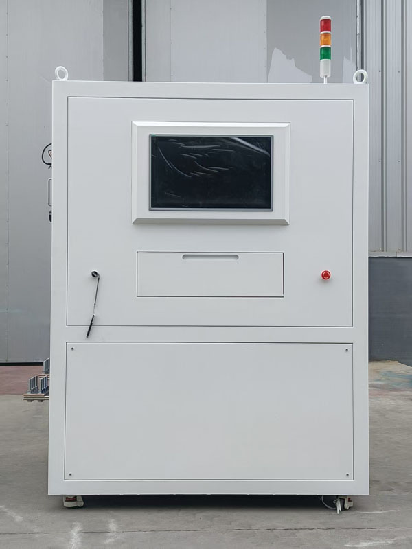
12) Operating environment: Temperature-10~50°C, humidity below 90%.4. Hardware system of NX-3000Q current transformer temperature rise testing device (automated current transformer temperature rise tester) consists of four main components: host computer, single-phase current source, adjustable load box, and DC resistance meter.
4. The hardware system of the test device NX-3000Q for current transformer temperature rise measurement (automated current transformer temperature rise test device) consists of four main components: a host computer, a single-phase current source, an adjustable load box, and a DC resistance meter.
5. Operational Procedure
1) Begin wiring according to the instructions in Section 6;
2) After wiring completion, manually adjust the corresponding load box to the transformer's designated setting;
3) Measure the secondary winding resistance of the current transformer (direct input if previously measured);
4) Initiate the temperature rise test by increasing current according to preset parameters;
5) Upon reaching the set current level, maintain current output while simultaneously recording temperature data for thermal balance evaluation;
6) When thermal equilibrium criteria are met, automatically terminate current output and disconnect secondary load circuits;
7) Activate the DC resistance tester circuit contactor to initiate testing;
8) Collect resistance readings at predetermined intervals until test duration concludes, marking successful temperature rise completion;
9) Software automatically calculates the instantaneous resistance value at power-off moment based on measured cooling resistance, derives winding temperature from this resistance value, and computes temperature rise through subtraction of ambient temperature averages during shutdown.
6. Software interface (using three-phase as reference)