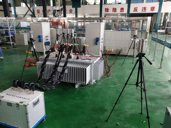
NX-II Transformer Temperature Rise Experimental Device
The technical solution for the NX-II transformer temperature rise test apparatus is designed for routine testing equipment of 10kV power transformers.
1.1 This technical solution is applicable to routine testing equipment for 10kV power transformers.
1.2 The technical specifications of this equipment outline minimum technical requirements without detailing all technical parameters or fully citing relevant standards and regulations. The supplier provides high-quality products compliant with national standards.
1.3 The purchaser shall provide a power transformer with the following specifications: model, capacity of 2500kVA, and voltage of 10kV.
2. Technical Requirements
1Environmental requirements
1.1 Ambient air temperature * Maximum temperature: not exceeding 40°C * Minimum temperature: not below-10°C
1.2 Altitude: below 1000m.
1.3 Air humidity: not exceeding 50% at +40℃.
1.4 Earthquake intensity: 7 degrees
2 Design and Production Implementation Standards and References
2.1 GB1094.1-1996 "Power Transformers-Part 1: General Principles"
2.2 GB1094.2-1996 "Power Transformers-Part 2: Temperature Rise"
2.3 JBT501-2006 "Test Guidelines for Power Transformers"
2.4 GB/T10228-1997 "Technical Parameters and Requirements for Dry-Type Power Transformers"
2.5 GB/T16927.1-2-1997 "High Voltage Testing Techniques-Part 2: Measurement Systems"
2.6 JB/T5472-1991 "Instrument Current Transformers" 2.7 JB/T5473-1991 "Instrument Voltage Transformers"
3. Test Protocol The test consists of a comprehensive control panel, induction voltage regulator, high-voltage precision transformer cabinet, low-voltage compensation capacitor cabinet, high-voltage test transformer, medium-frequency generator set, partial discharge detector, and other specialized testing instruments.
The integrated console serves as the control center for all peripheral devices in the system, enabling effective remote operation of equipment such as voltage regulators, while also providing functions including measurement, protection, and monitoring. Power supply current and voltage, as well as output current, voltage, and temperature measurements from the voltage regulator, are displayed on the control panel via digital instrument heads.
The system protection measures are safe and reliable. The main circuit is equipped with overcurrent and overvoltage protection, while the secondary side of the current transformer features overcurrent and grounding protection. The voltage regulator incorporates zero-position start-up protection.
PT1000 temperature sensors shall be pre-installed in each winding of the transformer.
4. Main Test Equipment Configuration
4.1 Test Equipment
4.1.1 NX-II/2500kVA Transformer Comprehensive Test Bench
4.1.2 NX-160kVA Three-phase Induction Voltage Regulator
4.1.3 NX301 Air Load Loss Meter
4.1.4 NXBYZ-10A Transformer DC Resistance Tester
4.1.5 NXBB-II Transformer Ratio Group Tester
4.1.6 Temperature Monitoring System with 16-channel Temperature Recorder
4.1.7 NXGY-120KV Experimental Transformer
4.1.8 NXBP-30KVA Generator Set (Triple Frequency)
4.1.9 Variable Frequency Dielectric Loss Tester NXJS-2000
4.1.10 Advantech Industrial Computer 4.1.11 Insulation Resistance Tester
5. Technical Specifications of Major Equipment
5.1 NX-II/2500kVA Transformer Test Bench
5.1.1 Capacity: 2500kVA Input voltage: Three-phase 380V.
5.1.2 The platform features an aesthetically designed structure with an external printer, built-in LCD display, SD301 no-load loss tester, DC resistance tester, and transformer ratio group tester for convenient measurement. Dimensions (mm): 1800×1200×800.
5.1.3 Voltage, current, and temperature measurement instruments are installed on the platform surface, along with a temperature rise timer.
5.1.4 All instruments are digital models with a measurement accuracy of Class 0.5.
5.2 Three-phase Voltage Regulator 160KVA
5.2.1 The voltage regulator features contactless voltage regulation, offering user-friendly operation and long-term reliable performance.
5.2.2 When the input voltage is constant, it can continuously and smoothly adjust the output voltage under load conditions.
5.2.3 Input voltage: three-phase 380V; output voltage: 0-650V; maximum load current: 222A.
5.2.4 The harmonic distortion generated by the voltage regulator to the power grid shall not exceed 3%, meeting the grid's requirements for power quality.
5.3 No-load Loss Tester
Main Features
The system employs a 240×64 dot matrix backlight LCD display, capable of simultaneously showing 18 electrical parameters including single-phase or three-phase voltage RMS values, voltage averages, current RMS values, active power, power factor, and frequency.
The multi-screen menu operation provides users with convenient selection options while automatically calculating various parameters, including P0, I0, Pkn, Pk120 (140)℃, ekt, e120℃, and ZK.
It can automatically correct voltage amplitude, waveform, and temperature.
The voltage and current transformer ratios can be set via buttons, with primary measurement values displayed directly.
The experiment date and transformer factory serial number can be set, and power-off latching is available.
It can measure power within the low power factor range.
Equipped with a print interface and a serial RS232 computer interface, the printing format complies with the standard record (Chinese characters) specifications.
It features strong anti-interference performance, overload alarm indication function, and reliable overvoltage and overcurrent protection, making it suitable for operation in field calibration environments.
Technical indicators (0.2 level)
Item | Measurement Range | Basic error |
Voltage | 700V | ±(0.1% reading + 0.1% range) |
Current | 5A | ±(0.1% reading + 0.1% range) |
Power | U×I | ±(0.2% reading + 0.1% range) |
Power Factor | 0.010~1.000 | ±3 characters |
Frequency | 45~65Hz | ±0.2% |
5.4 16-channel Color Screen Temperature Recorder 1) Sampling System: Current measurement employs Class 0.2 instruments and Class 0.2 current transformers, achieving overall system accuracy of Class 0.5. Temperature sampling utilizes a 40-channel or higher temperature tester with the following specifications:
◇ Temperature range: -50°C to 400°C
◇ Measurement accuracy: 0–400°C: ±(reading value × 0.2% + 1)°C; -50°C to 0°C: ±(reading value × 0.2% + 2)°C
◇ Features high-frequency interference resistance capability.
5.5 20A Transformer DC Resistance Tester (Dual Channel) This instrument employs innovative power supply technology, featuring compact size, lightweight design, and high output current. The entire system is microcontroller-controlled, automatically performing self-diagnosis, data processing, and display functions. With high measurement accuracy and user-friendly operation, it enables rapid measurement of transformer DC resistance.
5.51 Performance Features
1. High-voltage side output current: <15mA, 40mA, 200mA, 1A,5A; Low-voltage side output current: 2A,5A,10A,20A
2、Range: High pressure side:n 1mΩ~2Ω(5A)n 5mΩ~10Ω(1A)n 100mΩ~50Ω(200mA)n 1Ω~250Ω(40mA)n 10Ω~20kΩ(<15mA)low-pressure side:n 100μΩ~500mΩ(20A)n 200μΩ~1Ω(10A)n 1mΩ~1.6Ω(5A)n 5mΩ~4Ω(2A)
3. Precision: ±(0.2% + 2 digits)
4. Resolution: 0.1μΩ
5. Operating temperature: 0–40°C
6. Ambient humidity: ≤90% RH, no condensation
7. Power supply: AC220V ±10%,50Hz ±1Hz
8. Dimensions: 448*463*177 (mm)
5.6 Variable Ratio Group Tester (Panel Embedded)
The NX-II Type Transformer Ratio Group Quick Tester utilizes an advanced 80C196 microcontroller as its core component, automatically measuring various single-phase and three-phase transformers, voltage transformers, including their ratio values, ratio errors, polarity, as well as three-phase transformer ratios and group configurations. Powered by a single-phase power supply, the instrument internally generates a three-phase power source. During ratio testing for three-phase transformers and voltage transformers, its magnetic circuit configuration precisely replicates real-world applications, ensuring accurate measurement results. Featuring a fully Chinese-language interface, the device offers streamlined measurement processes and user-friendly operation.
Measurement range: Transformer ratio 1.0000–999.9; Groups: 1–12. Measurement accuracy: For transformer ratios between 1.0000 and 2000.0, accuracy is Class 0.2; for ratios between 2000.0 and 10000.0, accuracy is Class 0.5. Output voltage: AC190V; Maximum output current: AC0.25A. Operating power supply voltage: AC220V±22V; Frequency: 50Hz±2.5Hz. Ambient temperature range: -10°C to 50°C; Humidity: <90%. Dimensions: 380mm×280mm×206mm; Weight: 8kg.
5.7
Medium Frequency Generator Set SD Series Triple Frequency Test
1. Rated Capacity: 30KVA
2. Rated Line Voltage: 40~800V Three-phase Four-wire System
3. Synchronous Speed: 1500 rpm
4. Rated Power Factor: 0.5 (lagging)
5. Rated Frequency: 150 Hz
6. Rated Current: 21.7A
7. Protection Rating: IP21
8. Insulation Class: H
9. Output Connection: 6-terminal lead-out (with taps)
10. No-load Waveform Distortion Rate: ≤5%
11. Line Voltage Unbalance: ≤2%
12. Operating Mode: Short-time operation (2-hour cycle)
13. The generator voltage can be continuously and smoothly adjusted within the range of 10% to 110% of Un.
14. Rated excitation current: 1A 16. Rated excitation voltage: DC95V
3. Three-phase asynchronous motor (prime mover)
1. Model: NX
2. Power: 18.5kW
3. Rated voltage: 380V
4. Number of phases: 3
5. Number of poles: 4
6. Rated current: 3 5.9A
7. Rated speed: 1470 rpm
8. Rated power factor: 0.86
9. Connection type: 6-terminal connection
10. Insulation class: F-class5.8 Voltage Withstanding Capacity According to the *New Regulations*, a 10KVA 120KV transformer shall be selected. The original regulations specified a 10KVA 80KV transformer. The NXGY Series Lightweight AC High Voltage Test Transformer was developed based on the Ministry of Machinery and Electronics' "Test Transformer" standard, incorporating extensive improvements from existing counterparts. Specifications: Input: 0-220V Output: 120KVA Capacity: 10KVA
5.9 Dielectric Loss Tester Accuracy: Cx: ±(Reading × 1% + 1pF) tgδ: ±(Reading × 1% + 0.00040) Interference Resistance: Frequency conversion interference resistance, maintaining specified accuracy under 200% interference. Capacitance Range: Internal high voltage: 3pF~60000pF/10kV; 60pF~1μF/0.5kV External high voltage: 3pF~1.5μF/10kV; 60pF~30μF/0.5kV Resolution: Maximum 0.001pF (4 significant digits). tgδ range: Unlimited, resolution 0.001%. Automatic identification of capacitors, inductors, and resistors.
Test current range: 5μA to 5A. High voltage application: Set voltage range: 0.5 to 10kV. Maximum output current: 200mA. Voltage regulation method: Voltage can be arbitrarily set, e.g., 5123V.
Test frequency: Single frequency arbitrarily set within 40-70Hz, e.g., 48.7Hz.
Automatic dual-frequency adjustment ranging from 50±0.1Hz to 50±10Hz with flexible settings.
Automatic dual-frequency adjustment ranging from 60±0.1Hz to 60±10Hz.
Frequency accuracy: ±0.01Hz. External high voltage: Maximum test current 5A for forward wiring (power frequency or variable frequency 40-70Hz); maximum test current 10kV/5A for reverse wiring (power frequency or variable frequency 40-70Hz). Input power supply: 180V~270VAC, 50Hz ±1% (city power or generator). Computer interface: Standard RS232 interface with USB port (automatic data storage via USB).
Printer: Miniature thermal printer Ambient temperature: -10°C to 50°C Relative humidity: <90%